Saturday, September 17, 2016

Arduino based Antenna Rotator Controller - Latest Code


Well,  I updated the source code of the antenna rotator controller with magnetic declination entry and UI modifications.

1) Set Point Entry (Press * then enter the set point value and press # to confirm)
2) Inflight ( Hold Key 6 until the inflight filed become empty, then enter the Inflight and press# to confirm
3)Magnetic Declination angle (Hold Key 7 then enter the Magnetic Declination angle then # to confirm)
4) Magnetic Declination minute  (Hold Key 8 then enter the Magnetic Declination minute then # to confirm)
 5)Magnetic Declination East/West  (Hold Key -9 then enter the Magnetic Declination East/West (Press 1 for East and 2 for West) then # to confirm)
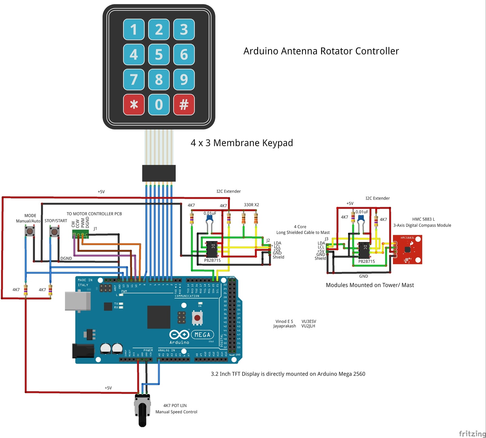
Image :


Source Code:


/*
 * An Arduino code  of Antenna Rotator Controller.
 * Copyright (c) 2016 Vinod E S (VU3ESV) , Jayaprakash L V (VU2JLH)
 * Version 1.0 - initial release
 * Version 1.1 - Inflight Entry after holding the "*" Key for 3 seconds
 * Version 10.0 - Magnetic Declination and Display restructuring
 * Version 11.0 - Key pad Entry changes
                 1) Press * then enter the Set Pont then # to confirm
                 2) Hold 6 then enter the Inflight then # to confirm
                 3) Hold 7 then enter the Magnetic Declination angle then # to confirm
                 4) Hold 8 then enter the Magnetic Declination minute then # to confirm
                 5) Hold 9 then enter the Magnetic Declination East/West (Press 1 for East and 2 for West) then # to confirm

 * Permission is hereby granted, free of charge, to any person obtaining a copy
 * of this software and associated documentation files (the "Software"), to deal
 * in the Software without restriction, including without limitation the rights
 * to use, copy, modify, merge, publish, distribute, sublicense, and/or sell
 * copies of the Software, and to permit persons to whom the Software is
 * furnished to do so, subject to the following conditions:
 *
 * The above copyright notice and this permission notice shall be included in
 * all copies or substantial portions of the Software.
 *
 * THE SOFTWARE IS PROVIDED "AS IS", WITHOUT WARRANTY OF ANY KIND, EXPRESS OR
 * IMPLIED, INCLUDING BUT NOT LIMITED TO THE WARRANTIES OF MERCHANTABILITY,
 * FITNESS FOR A PARTICULAR PURPOSE AND NONINFRINGEMENT. IN NO EVENT SHALL THE
 * AUTHORS OR COPYRIGHT HOLDERS BE LIABLE FOR ANY CLAIM, DAMAGES OR OTHER
 * LIABILITY, WHETHER IN AN ACTION OF CONTRACT, TORT OR OTHERWISE, ARISING FROM,
 * OUT OF OR IN CONNECTION WITH THE SOFTWARE OR THE USE OR OTHER DEALINGS IN
 * THE SOFTWARE.


 Harware Information :-

 1) Arduino Mega 2560R3 or its clones
 2) HMC5883L Accelerometer
 3) I2C Expander (NXP) P82B715
 4) 3.2 Inch TFT Display
 5) Momentary push button switchs with 4K7 pull up Resistors
 6) 4K7 Potentiometer
 7) Controller Circuit for Driving Motors see documents attached in this blog for a possible configuration
 */
#include <Wire.h> //I2C Arduino Library
#include <UTFT.h> // UTFT Library from Henning Karlsen (http://www.rinkydinkelectronics.com/library.php)
#include <UTFT_Geometry.h> //UTFT Geometry Library from Henning Karlsen (http://www.rinkydinkelectronics.com/library.php)
#include <Keypad.h>
#include <EEPROM.h>
const int X  = 320;
const int Y  = 160;
const int dm  = 130;
const int x_Offset = 30;
const int y_Offset = 128;
const int z_Offset = 0;
const byte rows = 4; // Four rows
const byte cols = 3; // Three columns
const int maxDegreeDigits = 3; //maximum allowed input length
const int fixedInflight = 5;
const long maxInflight = 25;
const long maxDeclinationDegree = 99;
const long maxDeclinationMinute = 59;
extern uint8_t BigFont[];
extern uint8_t SmallFont[];
extern uint8_t SevenSegmentFull[];
#define BLACK   0x0000
#define BLUE    0x001F
#define RED     0xF800
#define GREEN   0x07E0
#define CYAN    0x07FF
#define MAGENTA 0xF81F
#define YELLOW  0xFFE0
#define WHITE   0xFFFF
#define ORANGE  0xFF00
#define address 0x1E //0011110b, I2C 7bit address of HMC5883
#define EEPROM_ModeStatus_Location         10     // The starting address of the EEPROM where the data is Stored (10.11.12.13)
#define EEPROMSetpointLocation                 14
#define EEPROM_ScaleMax_Location                18
#define EEPROMInflightLocation                 22
#define EEPROMMagDeclinationDegreeLocation 26
#define EEPROMMagDeclinationMinuteLocation 30
#define EEPROMMagDeclinationSignLocation 34
struct EEPROMValue   //EEPROM Data Structure : Taken from G0MGX DDS VFO Code 
{
  union{
    long Value;
    struct
    {
      unsigned char Byte1;
      unsigned char Byte2;
      unsigned char Byte3;
      unsigned char Byte4;
    }
    __attribute__((packed));
  }
  __attribute__((packed));
}
__attribute__((packed));
inline long ReadEEPROMValue(int16_t EEPROMStartAddress);              //Reads the values from EEPROM Like Calibration , set Parameters, etc
inline void SaveEEPROMValue(int16_t EEPROMStartAddress, long Value);  //Save the Value to EEPROM startingfrom the given StartAddress (4 Bytes of Data)
inline long ReadAngleFromAccelerometer(int x_Offset, int y_Offset);
inline void ResetInputBuffer(void);
inline void DrawHead(int x2, int y2, int x1, int y1, int h, int w);
inline void DisplayUserEntry(int x, int y, String userData);
// Define the Keymap
char keys[rows][cols] =
{
  {
    '1','2','3'                                                    }
  ,
  {
    '4','5','6'                                                    }
  ,
  {
    '7','8','9'                                                    }
  ,
  {
    '*','0','#'                                                    }
};
boolean UserEntryStarted = false;
boolean UserEntryFinished = true;
boolean InflightEntryStarted = false;
boolean InflightEntryFinished = true;
boolean DeclinationDegEntryStarted = false;
boolean DeclinationDegEntryFinished = true;
boolean DeclinationMinEntryStarted = false;
boolean DeclinationMinEntryFinished = true;
boolean East_WestEntryStarted = false;
boolean East_WestEntryFinished = true;
boolean stopFlag = true;
boolean modeValue = false;    // modeValue = false (Manual Mode), modeValue = true (Auto Mode)
int inputSelection = 0; // 0  =  SetPoint Input , 1 = inflight input, 2 = magneticDeclenationDegree, 3 = magneticDeclenationMinute ,4  = EAST/WEST
char KeyEntries[3];         //3 characters to store 0 to 360 Degrees
char dataBuffer[60];
char formattedDataBuffer[3];
int dx;
int dy;
int fdx;
int fdy;
int bufPtr = 0;
int CWMotor  =  10;
int CCWMotor = 11;
int Stop_ResumeSignal = 12;
int Manual_Auto_Mode = 13;
int ManualSpeedControl = 9;
long UserEntry = 0;
long DegreeInput = 0;
long Inflight = 0;
long storedModeValue = 0;
long scaleMax  = 0;
long angle = 0;
long previousAngle;
int dxOuter, dyOuter, dxinner, dyinner;
int magneticDeclinationDegree = 0;
int magneticDeclinationMinute = 0;
int magneticDeclinationSign = 0;
//Normal Keyboard Connected To Arduino
// Connect keypad ROW0, ROW1, ROW2 and ROW3 to these Arduino pins.
byte rowPins[rows] = {
  8, 7, 6, 5 };
// Connect keypad COL0, COL1 and COL2 to these Arduino pins.
byte colPins[cols] = {
  4, 3, 2 };
Keypad keypad = Keypad( makeKeymap(keys), rowPins, colPins, rows, cols );
UTFT utftDisplay(ILI9481,38,39,40,41);
UTFT_Geometry geo(&utftDisplay);
#define  FormatData(x) strcpy_P(dataBuffer, PSTR(x))
void setup(){
  Serial.begin(9600);
  InitializeDisplay(); 
  InitializeKeypad(); 
  InitializeHMC5883();   
  delay(300);
  ConfigureIOPins();
  fdx = X;
  fdy = Y;
  previousAngle = 0;
  DrawInitialScreen();
  DegreeInput = ReadEEPROMValue(EEPROMSetpointLocation);
  Inflight = ReadEEPROMValue(EEPROMInflightLocation);
  if(Inflight<fixedInflight)
  {
    Inflight = fixedInflight;
  }
  storedModeValue = ReadEEPROMValue(EEPROM_ModeStatus_Location);
  scaleMax = ReadEEPROMValue(EEPROM_ScaleMax_Location);
  magneticDeclinationDegree = ReadEEPROMValue(EEPROMMagDeclinationDegreeLocation);
  magneticDeclinationMinute = ReadEEPROMValue(EEPROMMagDeclinationMinuteLocation);
  magneticDeclinationSign = ReadEEPROMValue(EEPROMMagDeclinationSignLocation);
  if (storedModeValue ==0)
  {
    modeValue = false; //Manual Mode
  }
  else if (storedModeValue == 1)
  {
    modeValue = true;  // AutoMode
  }
}
void loop()

  char key = keypad.getKey();
  angle = ReadAngleFromAccelerometer(x_Offset, y_Offset); 
  // 1 ArcMinute =  0.0166667 = Degrees
  if (magneticDeclinationSign == 1) // Magnetic Declination is POSITIVE (ie EAST)
  {
    angle = angle + ((magneticDeclinationDegree *60 + magneticDeclinationMinute)* 0.0166667) ;
  }
  else if(magneticDeclinationSign == 2)  // Magnetic Declination is NEGATIVE (ie WEST)
  {
    angle = angle -((magneticDeclinationDegree *60 *-1 + magneticDeclinationMinute)* 0.0166667) ;
  }
  if((digitalRead( Stop_ResumeSignal) == false)&& stopFlag == true)
  {
    stopFlag = false;
  }
  else if((digitalRead( Stop_ResumeSignal) == false)&& stopFlag == false)
  {   
    stopFlag = true;
  }
  if (stopFlag == true)
  {   
    digitalWrite(CWMotor,LOW);
    digitalWrite(CCWMotor,LOW);
    stopFlag = true;
    utftDisplay.setColor(0, 0, 0);
    utftDisplay.print("      ", RIGHT, 25);
  }
  else
  {
    if((angle< DegreeInput )&& stopFlag == false)
    {   
      digitalWrite(CWMotor,HIGH);
      digitalWrite(CCWMotor,LOW); 
      utftDisplay.setColor(0, 255, 255);
      utftDisplay.print("  CW ", RIGHT, 25);
    }
    if((angle >DegreeInput)&& stopFlag == false)
    {   
      digitalWrite(CWMotor,LOW);
      digitalWrite(CCWMotor,HIGH);
      utftDisplay.setColor(0, 255, 255);
      utftDisplay.print(" CCW ", RIGHT, 25);
    }
    if(( angle == DegreeInput)||
      ( angle > DegreeInput-Inflight)&&
      ( angle < DegreeInput+ Inflight ))  
    {   
      digitalWrite(CWMotor,LOW);
      digitalWrite(CCWMotor,LOW);
      stopFlag = true;
      utftDisplay.setColor(0, 0, 0);
      utftDisplay.print("      ", RIGHT, 25);
    }
  }
  if((digitalRead( Manual_Auto_Mode) == false) && modeValue == false )
  {
    modeValue = true;   
    SaveEEPROMValue(EEPROM_ModeStatus_Location, 1);
  }
  else if((digitalRead( Manual_Auto_Mode) == false) && modeValue == true )
  {
    modeValue = false;
    SaveEEPROMValue(EEPROM_ModeStatus_Location, 0);
  }
  if (modeValue ==  false)
  {
    if(stopFlag == false)
    {
      int spdValue = analogRead(A0);
      spdValue = map(spdValue, 0, 1023, 25 , 255);
      analogWrite(ManualSpeedControl, spdValue);
    }
    else
    {
      analogWrite(ManualSpeedControl, 0);
    }
    utftDisplay.setColor(0, 255, 255);
    utftDisplay.print("Manual ", RIGHT, 295);
  }
  else
  {
    if(stopFlag == false)
    {
      int rotationValue =(int)abs(DegreeInput-  angle); /* Irrespective of the Direction the difference in value needs to be considered for PWM
       // , Stoping is based on Cw/CCW outputs*/
      //Use Serial Print to check the value of rotationValue variable
      int scaleRotationValue =  rotationValue *8;
      int scaleMaxValue = scaleMax *8;
      int newSpeedValue = map(scaleRotationValue,0,scaleMaxValue, 30,255);   //The Scaling needs to be fine tuned based on the Test.     
      analogWrite(ManualSpeedControl, newSpeedValue);
    }
    else
    {
      analogWrite(ManualSpeedControl, 0);
    }
    utftDisplay.setColor(0, 255, 255);
    utftDisplay.print("    Auto ", RIGHT, 295);
  }
  utftDisplay.setFont(SevenSegmentFull);
  utftDisplay.setColor(255, 0, 127);
  int a = (int)angle;
  sprintf(formattedDataBuffer, FormatData("%03d"),a);
  utftDisplay.print(formattedDataBuffer, LEFT, 113);
  utftDisplay.setColor(RED);
  utftDisplay.drawCircle(320,160,9);
  utftDisplay.fillCircle(320,160,9);
  dx = (dm *.9 * cos((angle-90)*3.14/180)) + X;    // calculate X position
  dy = (dm *.9 * sin((angle-90)*3.14/180)) + Y;    // calculate Y position  
  utftDisplay.setColor(BLACK);
  DrawHead(fdx,fdy, X, Y, 10, 10);    // Erase Previous Head
  if( angle < (previousAngle + 2) && angle > (previousAngle - 2) )
  {
    delay(250);     
    angle = previousAngle;
  }
  utftDisplay.setColor(RED);
  DrawHead(dx,dy, X, Y, 10,10);       // Draw Head in new position
  fdx = dx;
  fdy = dy;
  previousAngle =  angle;
  if(UserEntryFinished == true)
  {
    utftDisplay.setFont(BigFont);
    utftDisplay.setColor(0, 255, 0);
    utftDisplay.printNumI(DegreeInput,100,175);
  } 
  if(InflightEntryFinished == true)
  {
    utftDisplay.setFont(BigFont);
    utftDisplay.setColor(0, 255, 0);
    utftDisplay.printNumI(Inflight,100,200);
  }
  if(DeclinationDegEntryFinished == true)
  {
    utftDisplay.setFont(BigFont);
    utftDisplay.setColor(0, 255, 0);
    utftDisplay.printNumI(magneticDeclinationDegree,100,230);
  } 
  if(DeclinationMinEntryFinished == true)
  {
    utftDisplay.setFont(BigFont);
    utftDisplay.setColor(0, 255, 0);
    utftDisplay.printNumI(magneticDeclinationMinute,142,230);
  }
  if(East_WestEntryFinished == true)
  {
    utftDisplay.setFont(BigFont);
    utftDisplay.setColor(0, 255, 0);
    if(magneticDeclinationSign == 1)
    {
      utftDisplay.print("E",180,230);
    }
    else if(magneticDeclinationSign == 2)
    {
      utftDisplay.print("W",180,230);
    }  
  }
  utftDisplay.setColor(0, 100, 255);
  if((angle < 22.5)  && (angle > 337.5 ))utftDisplay.print("     North", LEFT, 260);
  if((angle > 22.5)  && (angle < 67.5 )) utftDisplay.print("North-East", LEFT, 260);
  if((angle > 67.5)  && (angle < 112.5 ))utftDisplay.print("      East", LEFT, 260);
  if((angle > 112.5) && (angle < 157.5 ))utftDisplay.print("South-East", LEFT, 260);
  if((angle > 157.5) && (angle < 202.5 ))utftDisplay.print("     South", LEFT, 260);
  if((angle > 202.5) && (angle < 247.5 ))utftDisplay.print("South-West", LEFT, 260);
  if((angle > 247.5) && (angle < 292.5 ))utftDisplay.print("      West", LEFT, 260);
  if((angle > 292.5) && (angle < 337.5 ))utftDisplay.print("North-West", LEFT, 260);
}
void InitializeDisplay()
{
  utftDisplay.InitLCD();
  utftDisplay.InitLCD(LANDSCAPE);
  utftDisplay.clrScr(); 
  utftDisplay.setFont(BigFont);
  utftDisplay.setColor(255, 128, 0);
  utftDisplay.print("ANTENNA ROTATOR ", LEFT, 12);
  utftDisplay.print("CONTROLLER ", 40, 36);
  utftDisplay.drawLine(440, 160, 460, 160);
  utftDisplay.drawLine(180, 160, 200, 160);
  utftDisplay.drawLine(320, 20, 320, 40);
  utftDisplay.drawLine(320, 280, 320, 300);
  utftDisplay.drawCircle(320, 160, 130);
  utftDisplay.setColor(255, 255, 0);
  utftDisplay.print("BEAM DIR", LEFT, 75);
  utftDisplay.setFont(SmallFont);
  utftDisplay.setColor(255, 100, 100);
  utftDisplay.print("SET DIR", LEFT, 175);
  utftDisplay.print("INFLIGHT", LEFT, 200);
  utftDisplay.print("MAGNETIC",LEFT, 225);
  utftDisplay.print("DECLINATION",LEFT, 245);
  utftDisplay.setColor(255, 0, 0);
  utftDisplay.print("O", 130,  220); 
  utftDisplay.print("'", 175,  220);
  utftDisplay.setFont(BigFont); 
  utftDisplay.print("O", 95,  100);
  utftDisplay.setColor(255, 255, 255);
  utftDisplay.print("VU3ESV : VU2JLH",LEFT, 290); 
}
void InitializeKeypad()
{
  keypad.setDebounceTime(50);
  keypad.setHoldTime(3000);
  keypad.addEventListener(KeypadEventHandler); // Add an event listener for this keypad 
}
void InitializeHMC5883()
{
  // Initialize I2C communications
  Wire.begin();
  //Put the HMC5883 IC into the correct operating mode
  Wire.beginTransmission(address); //open communication with HMC5883
  Wire.write(0x02); //select mode register
  Wire.write(0x00); //continuous measurement mode
  Wire.endTransmission();
}
void ConfigureIOPins()
{
  pinMode(ManualSpeedControl, OUTPUT);
  pinMode(CWMotor,OUTPUT);
  digitalWrite(CWMotor,LOW);
  pinMode(CCWMotor,OUTPUT);
  digitalWrite(CCWMotor,LOW);
  pinMode(Manual_Auto_Mode,INPUT);
  pinMode(Stop_ResumeSignal,INPUT);
  analogReference(DEFAULT);
}
void DrawInitialScreen()
{
  utftDisplay.setColor(0, 255, 0);
  utftDisplay.drawCircle(X,Y,dm); 
  for (float i = 0; i <360; i = i + 22.5 )
  {
    utftDisplay.setColor(255, 128, 0);
    dxOuter = dm * cos((i-90)*3.14/180);
    dyOuter = dm * sin((i-90)*3.14/180);
    dxinner = dxOuter * 0.97;
    dyinner = dyOuter * 0.97;
    utftDisplay.drawLine(dxOuter+X,dyOuter+Y,dxinner+X,dyinner+Y);
  }
  for (float i = 0; i <360; i = i + 45 )
  {
    utftDisplay.setColor(255, 128, 0);
    dxOuter = dm * cos((i-90)*3.14/180);
    dyOuter = dm * sin((i-90)*3.14/180);
    dxinner = dxOuter * 0.92;
    dyinner = dyOuter * 0.92;
    utftDisplay.drawLine(dxinner+X,dyinner+Y,dxOuter+X,dyOuter+Y);
    DisplayUserEntry((X-8),(Y-157),"N");
    DisplayUserEntry((X-8),(Y+145),"S");
    DisplayUserEntry((X+141),(Y-7),"E");
    DisplayUserEntry((X-160),(Y-7),"W");
  }
}
void KeypadEventHandler(KeypadEvent key)
{
  if (key != NO_KEY)
  {
    switch (keypad.getState())
    {
    case IDLE:
    case RELEASED:
      break;
    case HOLD:
      switch (key)
      {
      case '6':
        utftDisplay.setFont(BigFont);
        utftDisplay.setColor(255, 0, 127);
        ResetInputBuffer();
        UserEntry = 0;
        utftDisplay.print("   ",100,200);
        InflightEntryStarted = true;
        InflightEntryFinished = false;
        inputSelection =1  ;            // Inflight
        break;
      case '7':
        utftDisplay.setFont(BigFont);
        utftDisplay.setColor(255, 0, 127);
        ResetInputBuffer();
        UserEntry = 0;         
        utftDisplay.print("   ",100,230);
        DeclinationDegEntryStarted = true;
        DeclinationDegEntryFinished = false;
        inputSelection = 2;          //Declination Degree
        break;
      case '8':
        utftDisplay.setFont(BigFont);
        utftDisplay.setColor(255, 0, 127);
        ResetInputBuffer();
        UserEntry = 0;         
        utftDisplay.print("   ",142,230);
        DeclinationMinEntryStarted = true;
        DeclinationMinEntryFinished = false;
        inputSelection = 3;          //Declination Minute              
        break;
      case '9':
        utftDisplay.setFont(BigFont);
        utftDisplay.setColor(255, 0, 127);
        ResetInputBuffer();
        UserEntry = 0;         
        utftDisplay.print("  ",180,230);
        East_WestEntryStarted = true;
        East_WestEntryFinished = false;
        inputSelection = 4;          //Declinatiom EAST/WEST
        break;
      }
      break;
    case PRESSED:
      switch (key)
      {
      case '#':
        if (inputSelection == 0)
        {
          UserEntryFinished = true;
          UserEntryStarted = false;
          if((UserEntry < 360) )
          {
            //If the User SetPoint is less than Inflight then we can't accept the set point
            if(UserEntry> Inflight)
            {
              DegreeInput = UserEntry;
              SaveEEPROMValue(EEPROMSetpointLocation, DegreeInput);
              scaleMax = abs( (int)(DegreeInput- (long) angle));
              SaveEEPROMValue (EEPROM_ScaleMax_Location, scaleMax);
              utftDisplay.setFont(BigFont);
              utftDisplay.setColor(BLACK);
              utftDisplay.print("    ",100,175);
              stopFlag = false; 
            }
            else
            {
              //Show Error in UI
            }     
          }
          else
          {
            utftDisplay.print("    ",100,175);
            DegreeInput = ReadEEPROMValue(EEPROMSetpointLocation);
          } 
          inputSelection = 0;
        }
        else if (inputSelection == 1)
        {
          InflightEntryFinished = true;
          InflightEntryStarted = false;
          if((UserEntry < maxInflight) )
          {
            Inflight = UserEntry;
            SaveEEPROMValue(EEPROMInflightLocation, Inflight);
            utftDisplay.setFont(BigFont);
            utftDisplay.setColor(BLACK);
            utftDisplay.print("    ",100,200);
            stopFlag = false;
          }
          else
          {
            utftDisplay.print("    ",100,200);
            Inflight = ReadEEPROMValue(EEPROMInflightLocation);
          }
          inputSelection = 0;
        }
        else if (inputSelection == 2)
        {
          DeclinationDegEntryFinished = true;
          DeclinationDegEntryStarted = false;
          if((UserEntry < maxDeclinationDegree) )
          {
            magneticDeclinationDegree = UserEntry;
            SaveEEPROMValue(EEPROMMagDeclinationDegreeLocation, magneticDeclinationDegree);
            utftDisplay.setFont(BigFont);
            utftDisplay.setColor(BLACK);
            utftDisplay.print("    ",100,230);
            stopFlag = false;
          }
          else
          {
            utftDisplay.print("    ",100,230);
            magneticDeclinationDegree = ReadEEPROMValue(EEPROMMagDeclinationDegreeLocation);
          }
          inputSelection = 0;
        }
        else if (inputSelection == 3)
        {
          DeclinationMinEntryFinished = true;
          DeclinationMinEntryStarted = false;
          if((UserEntry < maxDeclinationMinute) )
          {
            magneticDeclinationMinute = UserEntry;
            SaveEEPROMValue(EEPROMMagDeclinationMinuteLocation, magneticDeclinationMinute);
            utftDisplay.setFont(BigFont);
            utftDisplay.setColor(BLACK);
            utftDisplay.print("   ",142,230);
            stopFlag = false;
          }
          else
          {
            utftDisplay.print("   ",142,230);
            magneticDeclinationMinute = ReadEEPROMValue(EEPROMMagDeclinationMinuteLocation);
          }
          inputSelection = 0;
        }
        else if (inputSelection == 4)
        {
          East_WestEntryFinished = true;
          East_WestEntryStarted = false;
          if((UserEntry  == 1)||(UserEntry  == 2) )
          {
            magneticDeclinationSign = UserEntry;
            SaveEEPROMValue(EEPROMMagDeclinationSignLocation, magneticDeclinationSign);
            utftDisplay.setFont(BigFont);
            utftDisplay.setColor(BLACK);
            utftDisplay.print(" ",180,230);
            stopFlag = false;
          }
          else
          {
            utftDisplay.print("x",180,230);
            magneticDeclinationSign = ReadEEPROMValue(magneticDeclinationSign);
          }
          inputSelection = 0;
        }
        break;       
      case '*':
        if (inputSelection ==0)
        {
          utftDisplay.setFont(BigFont);
          utftDisplay.setColor(255, 0, 127);
          utftDisplay.print("   ",100,175);
          ResetInputBuffer();
          UserEntry = 0;
          UserEntryStarted = true;
          UserEntryFinished = false;
        }       
        break;
      case '0':
      case '1':
      case '2': 
      case '3':  
      case '4':
      case '5':
      case '6':
      case '7': 
      case '8':  
      case '9':
        if (bufPtr < maxDegreeDigits)
        {
          KeyEntries[bufPtr] = key;
          bufPtr++;           
          UserEntry = atol (KeyEntries);
          utftDisplay.setFont(BigFont);
          utftDisplay.setColor(255, 0, 127);
          if (UserEntryStarted == true)
          {
            utftDisplay.printNumI(UserEntry,100,175);
          }
          if (InflightEntryStarted == true)
          {
            utftDisplay.printNumI(UserEntry,100,200);
          }
          if (DeclinationDegEntryStarted == true)
          {
            utftDisplay.printNumI(UserEntry,100,230);
          }
          if (DeclinationMinEntryStarted == true)
          {
            utftDisplay.printNumI(UserEntry,142,230);
          }
          if (East_WestEntryStarted == true)
          {
            if(UserEntry == 1)
            {
              utftDisplay.print("E",180,230);
            }
            else if(UserEntry == 2)
            {
              utftDisplay.print("W",180,230);
            } 
          }
        }
        break;   
      }
      break;
    }
  }
}
long ReadAngleFromAccelerometer(int x_Offset, int y_Offset)
{
  //Tell the HMC5883 where to begin reading data
  Wire.beginTransmission(address);
  Wire.write(0x03); //select register 3, X MSB register
  Wire.endTransmission();
  //Read data from each axis, 2 registers per axis
  Wire.requestFrom(address, 6);
  int x,y,z; //triple axis data
  if(6<=Wire.available())
  {
    x = Wire.read() << 8 | Wire.read();
    z = Wire.read() << 8 | Wire.read();
    y = Wire.read() << 8 | Wire.read();
  }
  return atan2((double)y + y_Offset,(double)x + x_Offset)* (180 / 3.141592654) + 180;
}
void DisplayUserEntry(int x, int y, String userData)
{
  utftDisplay.setColor(RED);
  utftDisplay.setFont(BigFont);
  utftDisplay.print(userData,x,y);
}
void DrawHead(int x2, int y2, int x1, int y1, int h, int w)
{
  float dist;
  int dx, dy, x2a, y2a, x3, y3, x4, y4;
  dist = sqrt((x1 - x2)*(x1 - x2) + (y1 - y2)* (y1 - y2));
  dx = x1 + (w/6) * (x2 - x1) / h;
  dy = y1 + (w/6) * (y2 - y1) / h;
  x2a = x1 - dx;
  y2a = dy - y1;
  x3 = y2a + dx;
  y3 = x2a + dy;
  x4 = dx - y2a;
  y4 = dy - x2a;
  geo. drawTriangle(x2,y2,x3,y3,x4,y4);
  geo.fillTriangle(x2,y2,x3,y3,x4,y4);
}
void ResetInputBuffer()
{
  int length = sizeof(KeyEntries);
  for (int i = 0; i < length; i++)
  {
    KeyEntries[i] = '\0';
  }
  bufPtr = 0;
}
//Reads and returns the stored value specified in the EEPROM Start Address
long ReadEEPROMValue(int16_t EEPROMStartAddress)
{
  volatile EEPROMValue eepromVal;
  eepromVal.Byte1 = EEPROM.read(EEPROMStartAddress);
  eepromVal.Byte2 = EEPROM.read(EEPROMStartAddress+1);
  eepromVal.Byte3 = EEPROM.read(EEPROMStartAddress+2);
  eepromVal.Byte4 = EEPROM.read(EEPROMStartAddress+3);
  return eepromVal.Value;
}
/*Stores the specified value in the EEPROM  from Start Address
 EEPROM Write will only happens when the stored value and new value are different.
 This will save the number of Writes to the EEPROM.*/
void SaveEEPROMValue(int16_t EEPROMStartAddress, long Value)
{
  volatile EEPROMValue eepromVal;
  eepromVal.Value = ReadEEPROMValue(EEPROMStartAddress);
  if(eepromVal.Value != Value)
  {
    eepromVal.Value = Value;
    EEPROM.write(EEPROMStartAddress,eepromVal.Byte1);
    EEPROM.write(EEPROMStartAddress+1,eepromVal.Byte2);
    EEPROM.write(EEPROMStartAddress+2,eepromVal.Byte3);
    EEPROM.write(EEPROMStartAddress+3,eepromVal.Byte4);
  }
}

Hope this project helps :)

73's
DE VU3ESV
 

Thursday, June 9, 2016

Arduino antenna rotator controller -update.

I have used the SevensegmentFull.c from the below link. Please download it to the utft library folder to solve the compiler errors.

http://www.rinkydinkelectronics.com/r_fonts.php

VU3ESV

Tuesday, June 7, 2016

Arduino Mega2560 based Antenna Rotator Controller


Well after a long time I am back with a new project !

This is an attempt to build an Antenna rotator controller using Arduino Mega 2560 with a nice user interface showing the actual position of the antenna.

Idea of building a rotator controller is from my brother VU2JLH.

Following features are added in the controller project

1) Collect the Antenna position using HMC5883 Digital Compas
2) Auto/Manual mode operation . A potentiometer is used to control the speed in manual mode.
3) Stop/Resume inputs to pause the rotation and continue from that point.
4) 3.2 Inch TFT display
5) 3X4 Keypad for entering the target values.
6) Inflight entry to compensate the antenna rotation due to inertia.
7) I2C extender for long cable usage between shack and antenna.

HMC5883 will be attached to the antenna and a pair of I2C extenders are  used between the Arduino and HMC5883 . Use of I2C Extenders allow usage of long cable between shack and antenna tower.

3.2 inch TFT display is used for the UI. User can enter the Set point using the 3X4 Keypad.

Sequence to enter set-point is

1) Press the * key
2) Key in the  set-point value (0-360 deg)
3) Press the  # key

Controller will decide the rotation mode (clockwise or counter clockwise) based on the current position and set-point

An inflight value can be entered for stopping the Antenna before reaching the set point. This is applicable in case heavy antennas are controlled using this controller .

Sequence to enter inflight is hold the * key for 3 seconds, enter the inflight value , press the  # key.

Screen Shots


Schematics


Schematics of Motor Control Board


Source code of the Controller 

/*
 * An Arduino code  of Antenna Rotator Controller.
 * Copyright (c) 2016 Vinod E S (VU3ESV) , Jayaprakash L V (VU2JLH)
 * Version 1.0 - initial release
 * Version 1.1 - Inflight Entry after holding the "*" Key for 3 seconds

  * Permission is hereby granted, free of charge, to any person obtaining a copy
 * of this software and associated documentation files (the "Software"), to deal
 * in the Software without restriction, including without limitation the rights
 * to use, copy, modify, merge, publish, distribute, sublicense, and/or sell
 * copies of the Software, and to permit persons to whom the Software is
 * furnished to do so, subject to the following conditions:
 *
 * The above copyright notice and this permission notice shall be included in
 * all copies or substantial portions of the Software.
 *
 * THE SOFTWARE IS PROVIDED "AS IS", WITHOUT WARRANTY OF ANY KIND, EXPRESS OR
 * IMPLIED, INCLUDING BUT NOT LIMITED TO THE WARRANTIES OF MERCHANTABILITY,
 * FITNESS FOR A PARTICULAR PURPOSE AND NONINFRINGEMENT. IN NO EVENT SHALL THE
 * AUTHORS OR COPYRIGHT HOLDERS BE LIABLE FOR ANY CLAIM, DAMAGES OR OTHER
 * LIABILITY, WHETHER IN AN ACTION OF CONTRACT, TORT OR OTHERWISE, ARISING FROM,
 * OUT OF OR IN CONNECTION WITH THE SOFTWARE OR THE USE OR OTHER DEALINGS IN
 * THE SOFTWARE.


 Harware Information :-

 1) Arduino Mega 2560R3 or its clones
 2) HMC5883 Accelerometer
 3) I2C Expander (NXP)
 4) 2.8Inch TFT Display
 5) Momentary push button switchs
 6) Potentiometer
 7) H-Bridge for driving the Motors
 */

#include <Wire.h> //I2C Arduino Library
#include <UTFT.h> // UTFT Library from Henning Karlsen (http://www.rinkydinkelectronics.com/library.php)
#include <UTFT_Geometry.h> //UTFT Geometry Library from Henning Karlsen (http://www.rinkydinkelectronics.com/library.php)
#include <Keypad.h>
#include <EEPROM.h>

const int centreX  = 320;
const int centreY  = 160;
const int diameter = 130;
const int x_Offset = 30;
const int y_Offset = 128;
const int z_Offset = 0;
const byte rows = 4; // Four rows
const byte cols = 3; // Three columns
const int maxDegreeDigits = 3; //maximum allowed input length
const int fixedInflight = 5;
const long maxInflight = 25;

extern uint8_t BigFont[];
extern uint8_t SmallFont[];
extern uint8_t SevenSegmentFull[];

#define BLACK   0x0000
#define BLUE    0x001F
#define RED     0xF800
#define GREEN   0x07E0
#define CYAN    0x07FF
#define MAGENTA 0xF81F
#define YELLOW  0xFFE0
#define WHITE   0xFFFF
#define ORANGE  0xFF00
#define address 0x1E //0011110b, I2C 7bit address of HMC5883
#define EEPROM_ModeStatus_Location 10     // The starting address of the EEPROM where the data is Stored (10.11.12.13)
#define EEPROMSetpointLocation        14
#define EEPROM_ScaleMax_Location        18
#define EEPROMInflightLocation        22

struct EEPROMValue //EEPROM Data Structure : Taken from G0MGX DDS VFO Code
{
  union{
    long Value;
    struct
    {
      unsigned char Byte1;
      unsigned char Byte2;
      unsigned char Byte3;
      unsigned char Byte4;
    }
    __attribute__((packed));
  }
  __attribute__((packed));
}
__attribute__((packed));

inline long ReadEEPROMValue(int16_t EEPROMStartAddress);              //Reads the values from EEPROM Like Calibration , set Parameters, etc
inline void SaveEEPROMValue(int16_t EEPROMStartAddress, long Value);  //Save the Value to EEPROM startingfrom the given StartAddress (4 Bytes of Data)
inline double ReadAngleFromAccelerometer(int x_Offset, int y_Offset);
inline void ResetInputBuffer(void);

// Define the Keymap
char keys[rows][cols] =
{
  {
    '1','2','3'                 }
  ,
  {
    '4','5','6'                 }
  ,
  {
    '7','8','9'                 }
  ,
  {
    '*','0','#'                 }
};

boolean UserEntryStarted = false;
boolean UserEntryFinished = true;
boolean InflightEntryStarted = false;
boolean InflightEntryFinished = true;
boolean stopFlag = true;
boolean modeValue = false;    // modeValue = false (Manual Mode), modeValue = true (Auto Mode)
boolean inputSelection = false; // false  =  SetPoint Input , True = inflight input

char KeyEntries[3];        //3 characters to store 0 to 360 Degrees
char dataBuffer[60];
char formattedDataBuffer[3];

int dx;
int dy;
int last_dx;
int last_dy;
int bufPtr = 0;
int CWMotor  =  10;
int CCWMotor = 11;
int Stop_ResumeSignal = 12;
int Manual_Auto_Mode = 13;
int ManualSpeedControl = 9;

long UserEntry = 0;
long DegreeInput = 0;
long Inflight = 0;
long storedModeValue = 0;
long scaleMax  = 0;

double angle = 0;

//Normal Keyboard Connected To Arduino
// Connect keypad ROW0, ROW1, ROW2 and ROW3 to these Arduino pins.
byte rowPins[rows] = {
  8, 7, 6, 5 };
// Connect keypad COL0, COL1 and COL2 to these Arduino pins.
byte colPins[cols] = {
  4, 3, 2 };

Keypad keypad = Keypad( makeKeymap(keys), rowPins, colPins, rows, cols );

UTFT utftDisplay(ILI9481,38,39,40,41);

#define  FormatData(x) strcpy_P(dataBuffer, PSTR(x))

void setup(){
  Serial.begin(9600);
  utftDisplay.InitLCD();
  utftDisplay.InitLCD(LANDSCAPE);
  utftDisplay.clrScr();
  utftDisplay.setFont(BigFont);
  utftDisplay.setColor(255, 0, 0);
  utftDisplay.print("ANTENNA ROTATOR ", LEFT, 16);
  utftDisplay.print("CONTROLLER ", 40, 40);
  utftDisplay.drawLine(440, 160, 460, 160);
  utftDisplay.drawLine(180, 160, 200, 160);
  utftDisplay.drawLine(320, 20, 320, 40);
  utftDisplay.drawLine(320, 280, 320, 300);
  utftDisplay.setColor(255, 255, 0);
  utftDisplay.print("BEAM DIR", LEFT, 87);
  utftDisplay.setFont(SmallFont);
  utftDisplay.setColor(255, 100, 100);
  utftDisplay.print("SET DIR", LEFT, 210);
  utftDisplay.print("INFLIGHT", LEFT, 230);
  utftDisplay.setFont(BigFont);
  utftDisplay.setColor(255, 0, 0);
  utftDisplay.print("O", 95,  115);
  utftDisplay.setColor(255, 255, 255);
  utftDisplay.print("VU3ESV : VU2JLH",LEFT, 290);
  // Initialize I2C communications
  Wire.begin();
  //Put the HMC5883 IC into the correct operating mode
  Wire.beginTransmission(address); //open communication with HMC5883
  Wire.write(0x02); //select mode register
  Wire.write(0x00); //continuous measurement mode
  Wire.endTransmission();
  delay(300);
  last_dx = centreX;
  last_dy = centreY;

  DegreeInput = ReadEEPROMValue(EEPROMSetpointLocation);
  Inflight = ReadEEPROMValue(EEPROMInflightLocation);
  if(Inflight<fixedInflight)
  {
    Inflight = fixedInflight;
  }
  storedModeValue = ReadEEPROMValue(EEPROM_ModeStatus_Location);
  scaleMax = ReadEEPROMValue(EEPROM_ScaleMax_Location);
  if (storedModeValue ==0)
  {
    modeValue = false; //Manual Mode
  }
  else if (storedModeValue == 1)
  {
    modeValue = true;  // AutoMode
  }
  keypad.setDebounceTime(50);
  keypad.setHoldTime(3000);
  keypad.addEventListener(KeypadEventHandler); // Add an event listener for this keypad

  pinMode(ManualSpeedControl, OUTPUT);
  pinMode(CWMotor,OUTPUT);
  digitalWrite(CWMotor,LOW);
  pinMode(CCWMotor,OUTPUT);
  digitalWrite(CCWMotor,LOW);
  pinMode(Manual_Auto_Mode,INPUT);
  pinMode(Stop_ResumeSignal,INPUT);
  analogReference(DEFAULT);
}
double ReadAngleFromAccelerometer(int x_Offset, int y_Offset)
{
  //Tell the HMC5883 where to begin reading data
  Wire.beginTransmission(address);
  Wire.write(0x03); //select register 3, X MSB register
  Wire.endTransmission();
  //Read data from each axis, 2 registers per axis
  Wire.requestFrom(address, 6);
  int x,y,z; //triple axis data
  if(6<=Wire.available())
  {
    x = Wire.read() << 8 | Wire.read();
    z = Wire.read() << 8 | Wire.read();
    y = Wire.read() << 8 | Wire.read();
  }
  DrawRotatorPosition();
  return atan2((double)y + y_Offset,(double)x + x_Offset)* (180 / 3.141592654) + 180;
}
void loop()
{
  char key = keypad.getKey();
  angle = ReadAngleFromAccelerometer(y_Offset, x_Offset);
  if((digitalRead( Stop_ResumeSignal) == false)&& stopFlag == true)
  {
    stopFlag = false;
  }
  else if((digitalRead( Stop_ResumeSignal) == false)&& stopFlag == false)
  {  
    stopFlag = true;
  }
  if (stopFlag == true)
  {  
    digitalWrite(CWMotor,LOW);
    digitalWrite(CCWMotor,LOW);
    stopFlag = true;
    utftDisplay.setColor(0, 0, 0);
    utftDisplay.print("      ", RIGHT, 25);
  }
  else
  {
    if(((long)angle< DegreeInput )&& stopFlag == false)
    {  
      digitalWrite(CWMotor,HIGH);
      digitalWrite(CCWMotor,LOW);
      utftDisplay.setColor(0, 255, 255);
      utftDisplay.print("  CW ", RIGHT, 25);
    }
    if(((long)angle >DegreeInput)&& stopFlag == false)
    {  
      digitalWrite(CWMotor,LOW);
      digitalWrite(CCWMotor,HIGH);
      utftDisplay.setColor(0, 255, 255);
      utftDisplay.print(" CCW ", RIGHT, 25);
    }
    if(((long) angle == DegreeInput)||
      ((long) angle > DegreeInput-Inflight)&&
      ((long) angle < DegreeInput+ Inflight ))
    {  
      digitalWrite(CWMotor,LOW);
      digitalWrite(CCWMotor,LOW);
      stopFlag = true;
      utftDisplay.setColor(0, 0, 0);
      utftDisplay.print("      ", RIGHT, 25);
    }
  }
  if((digitalRead( Manual_Auto_Mode) == false) && modeValue == false )
  {
    modeValue = true;  
    SaveEEPROMValue(EEPROM_ModeStatus_Location, 1);
  }
  else if((digitalRead( Manual_Auto_Mode) == false) && modeValue == true )
  {
    modeValue = false;
    SaveEEPROMValue(EEPROM_ModeStatus_Location, 0);
  }
  if (modeValue ==  false)
  {
    if(stopFlag == false)
    {
      int spdValue = analogRead(A0);
      spdValue = map(spdValue, 0, 1023, 0 , 255);
      analogWrite(ManualSpeedControl, spdValue);
    }
    else
    {
      analogWrite(ManualSpeedControl, 0);
    }
    utftDisplay.setColor(0, 255, 255);
    utftDisplay.print("Manual ", RIGHT, 295);
  }
  else
  {
    if(stopFlag == false)
    {
      int rotationValue =abs( (int)(DegreeInput- (long) angle)); /* Irrespective of the Direction the difference in value needs to be considered for PWM
       // , Stoping is based on Cw/CCW outputs*/
      //Use Serial Print to check the value of rotationValue variable
      int scaleRotationValue =  rotationValue *4;
      int scaleMaxValue = scaleMax *4;
      int newSpeedValue = map(scaleRotationValue,0,scaleMaxValue, 0,255);   //The Scaling needs to be fine tuned based on the Test.    
      analogWrite(ManualSpeedControl, newSpeedValue);
    }
    else
    {
      analogWrite(ManualSpeedControl, 0);
    }
    utftDisplay.setColor(0, 255, 255);
    utftDisplay.print("    Auto ", RIGHT, 295);
  }
  dx = (diameter * cos((angle-90)*3.14/180)) + centreX;    // calculate X position
  dy = (diameter * sin((angle-90)*3.14/180)) + centreY;    // calculate Y position
  utftDisplay.setColor(BLACK);
  DrawArrow(last_dx,last_dy, centreX, centreY, 8, 8);        // Erase last arrow    
  utftDisplay.setColor(GREEN);
  DrawArrow(dx,dy, centreX, centreY, 8, 8);                  // Draw arrow in new position
  last_dx = dx;
  last_dy = dy;
  delay(25);
  utftDisplay.setFont(SevenSegmentFull);
  utftDisplay.setColor(255, 0, 127);
  int a =(int)angle;
  sprintf(formattedDataBuffer, FormatData("%03d"),a);
  utftDisplay.print(formattedDataBuffer, LEFT, 135);
  if(UserEntryFinished == true)
  {
    utftDisplay.setFont(BigFont);
    utftDisplay.setColor(0, 255, 0);
    utftDisplay.printNumI(DegreeInput,80,205);
  }
  if(InflightEntryFinished == true)
  {
    utftDisplay.setFont(BigFont);
    utftDisplay.setColor(0, 255, 0);
    utftDisplay.printNumI(Inflight,80,225);
  }
  utftDisplay.setFont(BigFont);
  utftDisplay.setColor(0, 100, 255);
  if((angle < 22.5)  || (angle > 337.5 ))utftDisplay.print("     North", LEFT, 260);
  if((angle > 22.5)  && (angle < 67.5 )) utftDisplay.print("North-East", LEFT, 260);
  if((angle > 67.5)  && (angle < 112.5 ))utftDisplay.print("      East", LEFT, 260);
  if((angle > 112.5) && (angle < 157.5 ))utftDisplay.print("South-East", LEFT, 260);
  if((angle > 157.5) && (angle < 202.5 ))utftDisplay.print("     South", LEFT, 260);
  if((angle > 202.5) && (angle < 247.5 ))utftDisplay.print("South-West", LEFT, 260);
  if((angle > 247.5) && (angle < 292.5 ))utftDisplay.print("      West", LEFT, 260);
  if((angle > 292.5) && (angle < 337.5 ))utftDisplay.print("North-West", LEFT, 260);
}

void KeypadEventHandler(KeypadEvent key)
{
  if (key != NO_KEY)
  {
    switch (keypad.getState())
    {
    case IDLE:
    case RELEASED:
      break;
    case HOLD:
      switch (key)
      {
        case '*':      
        if (inputSelection == true)
        {
          utftDisplay.setFont(BigFont);
          utftDisplay.setColor(255, 0, 127);
          utftDisplay.print("   ",80,225);
          ResetInputBuffer();
          UserEntry = 0;
          InflightEntryStarted = true;
          InflightEntryFinished = false;
        }
        break;
      }
      break;
    case PRESSED:
      switch (key)
      {
      case '#':
        if (inputSelection == false)
        {
          UserEntryFinished = true;
          UserEntryStarted = false;
          if((UserEntry < 360) )
          {
            //If the User SetPoint is less than Inflight then we can't accept the set point
            if(UserEntry> Inflight)
            {
              DegreeInput = UserEntry;
              SaveEEPROMValue(EEPROMSetpointLocation, DegreeInput);
              scaleMax = abs( (int)(DegreeInput- (long) angle));
              SaveEEPROMValue (EEPROM_ScaleMax_Location, scaleMax);
              utftDisplay.setFont(BigFont);
              utftDisplay.setColor(BLACK);
              utftDisplay.print("    ",80,205);
              stopFlag = false;
            }
            else
            {
              //Show Error in UI
            }    
          }
          else
          {
            utftDisplay.print("    ",80,205);
            DegreeInput = ReadEEPROMValue(EEPROMSetpointLocation);
          }
          inputSelection = true;
        }
        else
        {
          InflightEntryFinished = true;
          InflightEntryStarted = false;
          if((UserEntry < maxInflight) )
          {
            Inflight = UserEntry;
            SaveEEPROMValue(EEPROMInflightLocation, Inflight);
            utftDisplay.setFont(BigFont);
            utftDisplay.setColor(BLACK);
            utftDisplay.print("    ",80,225);
            stopFlag = false;
          }
          else
          {
            utftDisplay.print("    ",80,225);
            Inflight = ReadEEPROMValue(EEPROMInflightLocation);
          }
          inputSelection = false;
        }
        break;      
      case '*':
        if (inputSelection ==false)
        {
          utftDisplay.setFont(BigFont);
          utftDisplay.setColor(255, 0, 127);
          utftDisplay.print("   ",80,205);
          ResetInputBuffer();
          UserEntry = 0;
          UserEntryStarted = true;
          UserEntryFinished = false;
        }      
        break;
      case '0':
      case '1':
      case '2':
      case '3':
      case '4':
      case '5':
      case '6':
      case '7':
      case '8':
      case '9':
        if (bufPtr < maxDegreeDigits)
        {
          KeyEntries[bufPtr] = key;
          bufPtr++;          
          UserEntry = atol (KeyEntries);
          utftDisplay.setFont(BigFont);
          utftDisplay.setColor(255, 0, 127);
          if (UserEntryStarted == true)
          {
            utftDisplay.printNumI(UserEntry,80,205);
          }
          if (InflightEntryStarted == true)
          {
            utftDisplay.printNumI(UserEntry,80,225);
          }
        }
        break;  
      }
      break;
    }
  }
}

void DisplayUserEntry(int x, int y, String userData)
{
  utftDisplay.setColor(RED);
  utftDisplay.setFont(BigFont);
  utftDisplay.print(userData,x,y);
}

void DrawArrow(int x2, int y2, int x1, int y1, int arrowLength, int arrowWidth)
{
  float distance;
  int dx, dy, x2Outer,y2Outer,x3,y3,x4,y4,k;
  distance = sqrt(pow((x1 - x2), 2) + pow((y1 - y2), 2));
  dx = x2 + (x1 - x2) * arrowLength / distance;
  dy = y2 + (y1 - y2) * arrowLength / distance;
  k = arrowWidth / arrowLength;
  x2Outer = x2 - dx;
  y2Outer = dy - y2;
  x3 = y2Outer * k + dx;
  y3 = x2Outer * k + dy;
  x4 = dx - y2Outer * k;
  y4 = dy - x2Outer * k;
  utftDisplay.drawLine(x1, y1, x2, y2);
  utftDisplay.drawLine(x1, y1, dx, dy);
  utftDisplay.drawLine(x3, y3, x4, y4);
  utftDisplay.drawLine(x3, y3, x2, y2);
  utftDisplay.drawLine(x2, y2, x4, y4);
}

void DrawRotatorPosition()
{
  int dxOuter, dyOuter, dxi, dyi;
  utftDisplay.setColor(255, 128, 0);
  utftDisplay.drawCircle(centreX,centreY,diameter);  // Draw compass circle
  for (float i = 0; i <360; i = i + 22.5) {
    utftDisplay.setColor(255, 128, 0);
    dxOuter = diameter * cos((i-90)*3.14/180);
    dyOuter = diameter * sin((i-90)*3.14/180);
    dxi = dxOuter * 0.98;
    dyi = dyOuter * 0.98;
    utftDisplay.drawLine(dxi+centreX,dyi+centreY,dxOuter+centreX,dyOuter+centreY);
  }
  DisplayUserEntry((centreX-8),(centreY-157),"N");
  DisplayUserEntry((centreX-8),(centreY+145),"S");
  DisplayUserEntry((centreX+141),(centreY-7),"E");
  DisplayUserEntry((centreX-160),(centreY-7),"W");
}

void ResetInputBuffer()
{
  int length = sizeof(KeyEntries);
  for (int i = 0; i < length; i++)
  {
    KeyEntries[i] = '\0';
  }
  bufPtr = 0;
}

//Reads and returns the stored value specified in the EEPROM Start Address
long ReadEEPROMValue(int16_t EEPROMStartAddress)
{
  volatile EEPROMValue eepromVal;
  eepromVal.Byte1 = EEPROM.read(EEPROMStartAddress);
  eepromVal.Byte2 = EEPROM.read(EEPROMStartAddress+1);
  eepromVal.Byte3 = EEPROM.read(EEPROMStartAddress+2);
  eepromVal.Byte4 = EEPROM.read(EEPROMStartAddress+3);
  return eepromVal.Value;
}
/*Stores the specified value in the EEPROM  from Start Address
 EEPROM Write will only happens when the stored value and new value are different.
 This will save the number of Writes to the EEPROM.*/
void SaveEEPROMValue(int16_t EEPROMStartAddress, long Value)
{
  volatile EEPROMValue eepromVal;
  eepromVal.Value = ReadEEPROMValue(EEPROMStartAddress);
  if(eepromVal.Value != Value)
  {
    eepromVal.Value = Value;
    EEPROM.write(EEPROMStartAddress,eepromVal.Byte1);
    EEPROM.write(EEPROMStartAddress+1,eepromVal.Byte2);
    EEPROM.write(EEPROMStartAddress+2,eepromVal.Byte3);
    EEPROM.write(EEPROMStartAddress+3,eepromVal.Byte4);
  }
}


I have used the UTFT library from Henning Karlsen  (Rinky-Dink Electronics) and the same has to be downloaded before compiling the sketch.

Please note : This code is not meant for any commercial use.

Wednesday, February 17, 2016

VFO + Radio Controller

Couple of months back I have created a prototype board for Si570. I had plan to use the Arduino Mega or mBed to drive the Si570.

Both of the options worked well, in fact the mBed based prototype was very small in and can fit in to a pencil box.

After driving the Si570 from the Arduino Mega, I thought of adding a Display to configure/view the frequency. Adding a 20x4 LCD was the initial decision, later changed to a 480x320 TFT.
 Arduino Mega has lot of pins which could be used for controlling the Band Pass Filter, Low Pass Filter, Tx/Rx control etc.

Here is the list of parts/functions which I am planning to add in this build to extend the VFO to a full functional Radio Controller

1) 4x4 KeyPad for frequency entry/selection of other radio functions/configuration/setup
2) 480x320 TFT display .(3.2 or 2.8 inch)
3) Tx/Rx switching , display the same in LCD
4) Band Output to select the BPF/LPF
5) RIT
6) VFO-A/B/SPLIT mode.
7) CAT interface
8) VFO-Memory and vice-versa
9) S-Meter for Signal strength
10) LSB/USB indication
11) AGC On/Off Control
12) PreAmp On/Off Control
13) RIT On/Off Control
14) Attenuator On/Off Control
15) Noise Blanker On/Off Control

Following Menu/ Setup Parameters are also considered at the moment.

1) IF Offset
2) VFO Mode - Possible options are (a) VFO-IF, (b) IF-VFO
3) RIT settings
4) SSB Offset Settings
5) High /Low Frequency Settings ( optional)
6) Band Settings (configured with default band plan,but can be altered based on user). This option can be used if the LPF/BPF is avilable certain HF bands.
7) Call Sign


A basic design of the UI is attached here.


Time to write a Radio Contrroller Library for Arduino :)


Sunday, January 4, 2015

Si570 Prototype Board

Si570 from Silicon Labs is a nice oscillator in terms of stability and frequency range.

I got 2 Si570s(CMOS Version 10 MHz to 160 MHz) for my project and I decided to make a prototype oscillator for my experiments.

Since Si570 operates in 3.3V (again for CMOS only) I had to find a level shifter for the SDA and SCL lines. With out the I2C level shifter I will not be able to drive the Si570 from an Arduino Mega.


I have used this level shifter with slight modifications :)

2N7000 is used in place of BSS138, and 4.7K is used instead of 10K.


 LM1117 is used for the 3.3 V regulated supply.

Si570 is not directly soldered, It is hanging in the air :)

As you can see the two output connectors are connected to the CLK+ and CLK- pins of the Si570. Later I realized that the CLK- output is not used in the CMOS version, so I connected the SMA connector to CLK+.

For initial testing the Prototype board is connected to a 5V supply and the Racal Frequency counter indicates 56.3 MHz (based on the factory programmed register values).

Now it is time to write some code to control the Si570.

I need to test the following scenarios

1) Arduino Mega + Si570 + Optical Encoder + KO7M's Si570 library
2) NXP mBed + Si570 + Optical Encoder +  mBed Si570 Library
3) Stm32F429 Discovery + .Net MicroFramework + Si570 + Si570 .net Library ( I have ported K07M 's lib to C#)

I hope I will be able to post the test results soon....


Wednesday, September 24, 2014

Arduino DDS Signal Generarator - Modifications

              Well, I was thinking about how to reduce the "wire mesh" from the Signal Generator. One option is to interface the 20x4 LCD using an I2C expander. I can use the MCP23017 16I/O or a PCF8574 from NXP. Decision is to go ahead with the PCF8574. 

Next target is to improve the Keypad handling.   Here also I can use the same chip to handle a 4x4 matrix keyboard

There are libraries available for I2C LCD and Keypad targeting the PCF8574.

Next experiment is to evaluate the libraries before making any change to the code...:)


Sunday, September 21, 2014

Arduino DDS Signal Generator

An attempt to create a Signal generator for my BitX MK2 testing..

I had considered the following requirements

   1) Tuning based on an Encoder;
   2) 20x4 LCD
   3) Memory for specific channels
   4) Arduino based
   5) Keyboard for frequency entry
   6) DDS chip as frequency generator.


I prefer to use the optical encoder instead of a mechanical one. Mechanical encoder fails to work after continuous operation. Sometimes I need to open the mechanical encoder and clean it for a better control. 

Regarding the LCD, initially I thought of using an I2C/Serial LCD, but I could not find one in the local market. So I decided to use the 20x4 LCD which was lying in the junk for a while. Today I saw one convertor for LCD in KO7M's blog ( I am not sure whether it is I2C or RS232 version).

My plan was to use a Atmega328(with preloaded arduino boot loader) , but this needs a PCB and supporting components :). Finally I decided to go ahead with an Arduino Mega 2560R3. This is a nice board with 256KB of flash well enough for my application.

A flexible 3x4 keyboard is used in the build, in future it will be replaced with a 4x4 keyboard ( depending on the pin availability in Mega 2560)

Sometime back I had procured a DDS board from Digibay.in. It uses the AD9850 DDS chip and a 125 MHz crystal oscillator. The DDS board needs a 3.3 volt power supply, which I realized at a later point :). I didn't had a 3.3 v regulator ( through hole type) , so I used 2 1N4147 diodes in series and connected to the DDS power pin. For time being this can solve the heating issue of DDS board.

For testing the Radio I need to generate an LSB /USB signals ( to be frank this is also not needed, but it will be good as the frequency display in the Radio and the Signal generator will match).In the Firmware I have considered an option to switch the LSB/USB frequencies too.

Once this is completed then I can extend the features of this signal generator by adding the RIT, additional input for Tx/Rx indication, Tx Power lever in LCD etc.


It looks like a wire mesh :), but the build is working fine...
May be it is worth to show some LCD Screen shots


I have written a calibration routine for the DDS and the values are stored in the EPROM of Mega 2560.

I have used the Encoder Library from http://www.pjrc.com/teensy/td_libs_Encoder.html. I have made couple of modifications in the original library based on my requirements.

Another custom library used in the project is to drive the DDS Chip.

I don't use a Git repository , so f anybody interested to try this build or expand it for your requirements please drop me a mail to vinodes "at" aol "dot"com ( don't forget to replace the "at" and "dot" :) ) I will be happy to give the source code and the libraries.


Problems observed :

1) When the DDS chip is operational for some time (say for one hour) the frequency is shifting for a couple of Hz. This may not be a problem if it is used in a radio. But for a signal generator point of view, it should be rock solid. I doubt the DDS board, it is a made in China borard , it costs only INR 500. If I have to buy a DDS chip from Farnell then I have to pay almost double money :)

One solution for this problem is to use the SiLabs Si570 which works from 10MHz to 160 MHz ( needs 3.3 v Power + an I2C level shifter) .
Trigger for another project :).........