Well after a long time I am back with a new project !
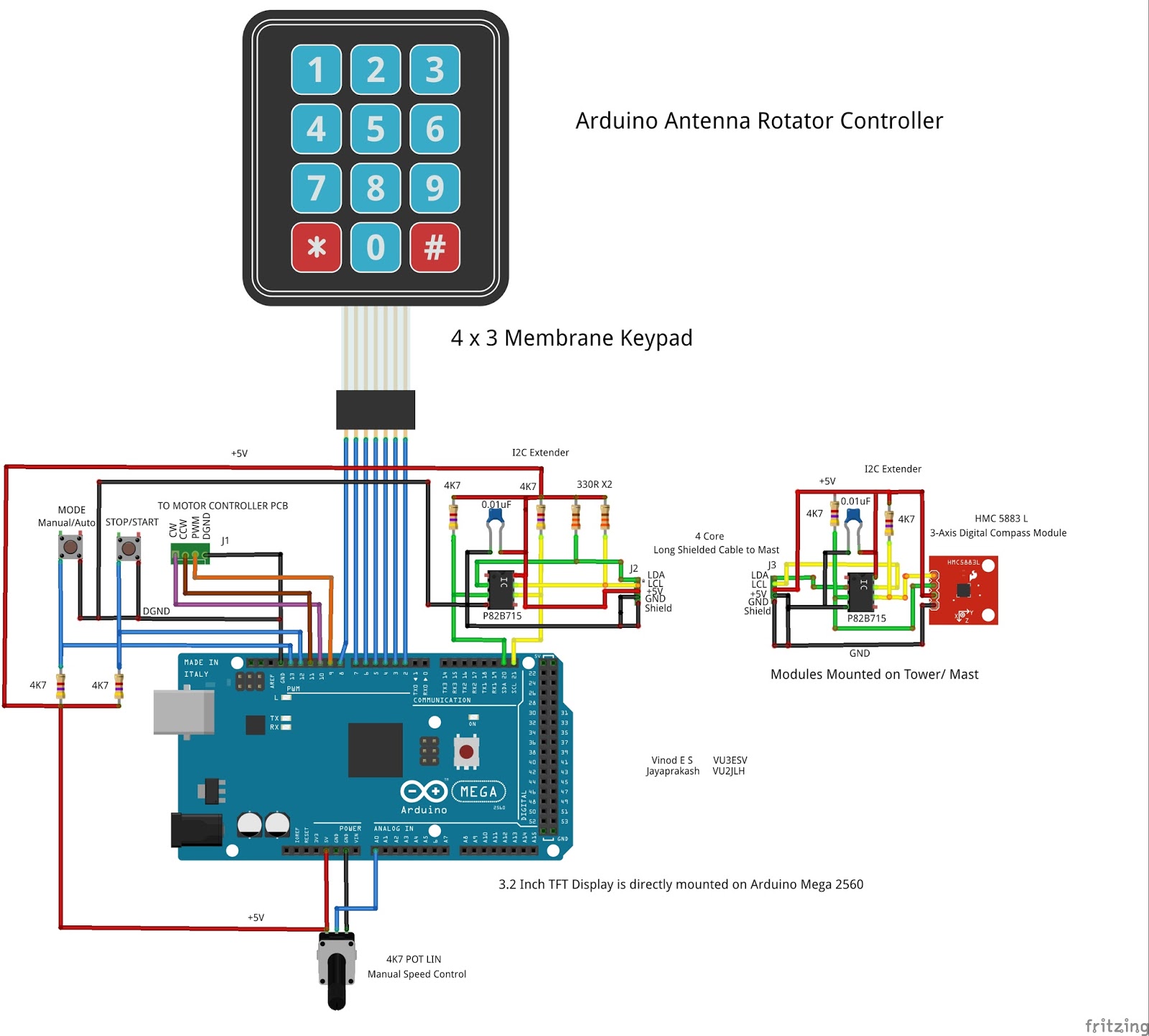
This is an attempt to build an Antenna rotator controller using Arduino Mega 2560 with a nice user interface showing the actual position of the antenna.
Idea of building a rotator controller is from my brother VU2JLH.
Following features are added in the controller project
1) Collect the Antenna position using HMC5883 Digital Compas
2) Auto/Manual mode operation . A potentiometer is used to control the speed in manual mode.
3) Stop/Resume inputs to pause the rotation and continue from that point.
4) 3.2 Inch TFT display
5) 3X4 Keypad for entering the target values.
6) Inflight entry to compensate the antenna rotation due to inertia.
7) I2C extender for long cable usage between shack and antenna.
HMC5883 will be attached to the antenna and a pair of I2C extenders are used between the Arduino and HMC5883 . Use of I2C Extenders allow usage of long cable between shack and antenna tower.
3.2 inch TFT display is used for the UI. User can enter the Set point using the 3X4 Keypad.
Sequence to enter set-point is
1) Press the * key
2) Key in the set-point value (0-360 deg)
3) Press the # key
Controller will decide the rotation mode (clockwise or counter clockwise) based on the current position and set-point
An inflight value can be entered for stopping the Antenna before reaching the set point. This is applicable in case heavy antennas are controlled using this controller .
Sequence to enter inflight is hold the * key for 3 seconds, enter the inflight value , press the # key.
Screen Shots

Schematics
Schematics of Motor Control Board

Source code of the Controller
/*
* An Arduino code of Antenna Rotator Controller.
* Copyright (c) 2016 Vinod E S (VU3ESV) , Jayaprakash L V (VU2JLH)
* Version 1.0 - initial release
* Version 1.1 - Inflight Entry after holding the "*" Key for 3 seconds
* Permission is hereby granted, free of charge, to any person obtaining a copy
* of this software and associated documentation files (the "Software"), to deal
* in the Software without restriction, including without limitation the rights
* to use, copy, modify, merge, publish, distribute, sublicense, and/or sell
* copies of the Software, and to permit persons to whom the Software is
* furnished to do so, subject to the following conditions:
*
* The above copyright notice and this permission notice shall be included in
* all copies or substantial portions of the Software.
*
* THE SOFTWARE IS PROVIDED "AS IS", WITHOUT WARRANTY OF ANY KIND, EXPRESS OR
* IMPLIED, INCLUDING BUT NOT LIMITED TO THE WARRANTIES OF MERCHANTABILITY,
* FITNESS FOR A PARTICULAR PURPOSE AND NONINFRINGEMENT. IN NO EVENT SHALL THE
* AUTHORS OR COPYRIGHT HOLDERS BE LIABLE FOR ANY CLAIM, DAMAGES OR OTHER
* LIABILITY, WHETHER IN AN ACTION OF CONTRACT, TORT OR OTHERWISE, ARISING FROM,
* OUT OF OR IN CONNECTION WITH THE SOFTWARE OR THE USE OR OTHER DEALINGS IN
* THE SOFTWARE.
Harware Information :-
1) Arduino Mega 2560R3 or its clones
2) HMC5883 Accelerometer
3) I2C Expander (NXP)
4) 2.8Inch TFT Display
5) Momentary push button switchs
6) Potentiometer
7) H-Bridge for driving the Motors
*/
#include <Wire.h> //I2C Arduino Library
#include <UTFT.h> // UTFT Library from Henning Karlsen (http://www.rinkydinkelectronics.com/library.php)
#include <UTFT_Geometry.h> //UTFT Geometry Library from Henning Karlsen (http://www.rinkydinkelectronics.com/library.php)
#include <Keypad.h>
#include <EEPROM.h>
const int centreX = 320;
const int centreY = 160;
const int diameter = 130;
const int x_Offset = 30;
const int y_Offset = 128;
const int z_Offset = 0;
const byte rows = 4; // Four rows
const byte cols = 3; // Three columns
const int maxDegreeDigits = 3; //maximum allowed input length
const int fixedInflight = 5;
const long maxInflight = 25;
extern uint8_t BigFont[];
extern uint8_t SmallFont[];
extern uint8_t SevenSegmentFull[];
#define BLACK 0x0000
#define BLUE 0x001F
#define RED 0xF800
#define GREEN 0x07E0
#define CYAN 0x07FF
#define MAGENTA 0xF81F
#define YELLOW 0xFFE0
#define WHITE 0xFFFF
#define ORANGE 0xFF00
#define address 0x1E //0011110b, I2C 7bit address of HMC5883
#define EEPROM_ModeStatus_Location 10 // The starting address of the EEPROM where the data is Stored (10.11.12.13)
#define EEPROMSetpointLocation 14
#define EEPROM_ScaleMax_Location 18
#define EEPROMInflightLocation 22
struct EEPROMValue //EEPROM Data Structure : Taken from G0MGX DDS VFO Code
{
union{
long Value;
struct
{
unsigned char Byte1;
unsigned char Byte2;
unsigned char Byte3;
unsigned char Byte4;
}
__attribute__((packed));
}
__attribute__((packed));
}
__attribute__((packed));
inline long ReadEEPROMValue(int16_t EEPROMStartAddress); //Reads the values from EEPROM Like Calibration , set Parameters, etc
inline void SaveEEPROMValue(int16_t EEPROMStartAddress, long Value); //Save the Value to EEPROM startingfrom the given StartAddress (4 Bytes of Data)
inline double ReadAngleFromAccelerometer(int x_Offset, int y_Offset);
inline void ResetInputBuffer(void);
// Define the Keymap
char keys[rows][cols] =
{
{
'1','2','3' }
,
{
'4','5','6' }
,
{
'7','8','9' }
,
{
'*','0','#' }
};
boolean UserEntryStarted = false;
boolean UserEntryFinished = true;
boolean InflightEntryStarted = false;
boolean InflightEntryFinished = true;
boolean stopFlag = true;
boolean modeValue = false; // modeValue = false (Manual Mode), modeValue = true (Auto Mode)
boolean inputSelection = false; // false = SetPoint Input , True = inflight input
char KeyEntries[3]; //3 characters to store 0 to 360 Degrees
char dataBuffer[60];
char formattedDataBuffer[3];
int dx;
int dy;
int last_dx;
int last_dy;
int bufPtr = 0;
int CWMotor = 10;
int CCWMotor = 11;
int Stop_ResumeSignal = 12;
int Manual_Auto_Mode = 13;
int ManualSpeedControl = 9;
long UserEntry = 0;
long DegreeInput = 0;
long Inflight = 0;
long storedModeValue = 0;
long scaleMax = 0;
double angle = 0;
//Normal Keyboard Connected To Arduino
// Connect keypad ROW0, ROW1, ROW2 and ROW3 to these Arduino pins.
byte rowPins[rows] = {
8, 7, 6, 5 };
// Connect keypad COL0, COL1 and COL2 to these Arduino pins.
byte colPins[cols] = {
4, 3, 2 };
Keypad keypad = Keypad( makeKeymap(keys), rowPins, colPins, rows, cols );
UTFT utftDisplay(ILI9481,38,39,40,41);
#define FormatData(x) strcpy_P(dataBuffer, PSTR(x))
void setup(){
Serial.begin(9600);
utftDisplay.InitLCD();
utftDisplay.InitLCD(LANDSCAPE);
utftDisplay.clrScr();
utftDisplay.setFont(BigFont);
utftDisplay.setColor(255, 0, 0);
utftDisplay.print("ANTENNA ROTATOR ", LEFT, 16);
utftDisplay.print("CONTROLLER ", 40, 40);
utftDisplay.drawLine(440, 160, 460, 160);
utftDisplay.drawLine(180, 160, 200, 160);
utftDisplay.drawLine(320, 20, 320, 40);
utftDisplay.drawLine(320, 280, 320, 300);
utftDisplay.setColor(255, 255, 0);
utftDisplay.print("BEAM DIR", LEFT, 87);
utftDisplay.setFont(SmallFont);
utftDisplay.setColor(255, 100, 100);
utftDisplay.print("SET DIR", LEFT, 210);
utftDisplay.print("INFLIGHT", LEFT, 230);
utftDisplay.setFont(BigFont);
utftDisplay.setColor(255, 0, 0);
utftDisplay.print("O", 95, 115);
utftDisplay.setColor(255, 255, 255);
utftDisplay.print("VU3ESV : VU2JLH",LEFT, 290);
// Initialize I2C communications
Wire.begin();
//Put the HMC5883 IC into the correct operating mode
Wire.beginTransmission(address); //open communication with HMC5883
Wire.write(0x02); //select mode register
Wire.write(0x00); //continuous measurement mode
Wire.endTransmission();
delay(300);
last_dx = centreX;
last_dy = centreY;
DegreeInput = ReadEEPROMValue(EEPROMSetpointLocation);
Inflight = ReadEEPROMValue(EEPROMInflightLocation);
if(Inflight<fixedInflight)
{
Inflight = fixedInflight;
}
storedModeValue = ReadEEPROMValue(EEPROM_ModeStatus_Location);
scaleMax = ReadEEPROMValue(EEPROM_ScaleMax_Location);
if (storedModeValue ==0)
{
modeValue = false; //Manual Mode
}
else if (storedModeValue == 1)
{
modeValue = true; // AutoMode
}
keypad.setDebounceTime(50);
keypad.setHoldTime(3000);
keypad.addEventListener(KeypadEventHandler); // Add an event listener for this keypad
pinMode(ManualSpeedControl, OUTPUT);
pinMode(CWMotor,OUTPUT);
digitalWrite(CWMotor,LOW);
pinMode(CCWMotor,OUTPUT);
digitalWrite(CCWMotor,LOW);
pinMode(Manual_Auto_Mode,INPUT);
pinMode(Stop_ResumeSignal,INPUT);
analogReference(DEFAULT);
}
double ReadAngleFromAccelerometer(int x_Offset, int y_Offset)
{
//Tell the HMC5883 where to begin reading data
Wire.beginTransmission(address);
Wire.write(0x03); //select register 3, X MSB register
Wire.endTransmission();
//Read data from each axis, 2 registers per axis
Wire.requestFrom(address, 6);
int x,y,z; //triple axis data
if(6<=Wire.available())
{
x = Wire.read() << 8 | Wire.read();
z = Wire.read() << 8 | Wire.read();
y = Wire.read() << 8 | Wire.read();
}
DrawRotatorPosition();
return atan2((double)y + y_Offset,(double)x + x_Offset)* (180 / 3.141592654) + 180;
}
void loop()
{
char key = keypad.getKey();
angle = ReadAngleFromAccelerometer(y_Offset, x_Offset);
if((digitalRead( Stop_ResumeSignal) == false)&& stopFlag == true)
{
stopFlag = false;
}
else if((digitalRead( Stop_ResumeSignal) == false)&& stopFlag == false)
{
stopFlag = true;
}
if (stopFlag == true)
{
digitalWrite(CWMotor,LOW);
digitalWrite(CCWMotor,LOW);
stopFlag = true;
utftDisplay.setColor(0, 0, 0);
utftDisplay.print(" ", RIGHT, 25);
}
else
{
if(((long)angle< DegreeInput )&& stopFlag == false)
{
digitalWrite(CWMotor,HIGH);
digitalWrite(CCWMotor,LOW);
utftDisplay.setColor(0, 255, 255);
utftDisplay.print(" CW ", RIGHT, 25);
}
if(((long)angle >DegreeInput)&& stopFlag == false)
{
digitalWrite(CWMotor,LOW);
digitalWrite(CCWMotor,HIGH);
utftDisplay.setColor(0, 255, 255);
utftDisplay.print(" CCW ", RIGHT, 25);
}
if(((long) angle == DegreeInput)||
((long) angle > DegreeInput-Inflight)&&
((long) angle < DegreeInput+ Inflight ))
{
digitalWrite(CWMotor,LOW);
digitalWrite(CCWMotor,LOW);
stopFlag = true;
utftDisplay.setColor(0, 0, 0);
utftDisplay.print(" ", RIGHT, 25);
}
}
if((digitalRead( Manual_Auto_Mode) == false) && modeValue == false )
{
modeValue = true;
SaveEEPROMValue(EEPROM_ModeStatus_Location, 1);
}
else if((digitalRead( Manual_Auto_Mode) == false) && modeValue == true )
{
modeValue = false;
SaveEEPROMValue(EEPROM_ModeStatus_Location, 0);
}
if (modeValue == false)
{
if(stopFlag == false)
{
int spdValue = analogRead(A0);
spdValue = map(spdValue, 0, 1023, 0 , 255);
analogWrite(ManualSpeedControl, spdValue);
}
else
{
analogWrite(ManualSpeedControl, 0);
}
utftDisplay.setColor(0, 255, 255);
utftDisplay.print("Manual ", RIGHT, 295);
}
else
{
if(stopFlag == false)
{
int rotationValue =abs( (int)(DegreeInput- (long) angle)); /* Irrespective of the Direction the difference in value needs to be considered for PWM
// , Stoping is based on Cw/CCW outputs*/
//Use Serial Print to check the value of rotationValue variable
int scaleRotationValue = rotationValue *4;
int scaleMaxValue = scaleMax *4;
int newSpeedValue = map(scaleRotationValue,0,scaleMaxValue, 0,255); //The Scaling needs to be fine tuned based on the Test.
analogWrite(ManualSpeedControl, newSpeedValue);
}
else
{
analogWrite(ManualSpeedControl, 0);
}
utftDisplay.setColor(0, 255, 255);
utftDisplay.print(" Auto ", RIGHT, 295);
}
dx = (diameter * cos((angle-90)*3.14/180)) + centreX; // calculate X position
dy = (diameter * sin((angle-90)*3.14/180)) + centreY; // calculate Y position
utftDisplay.setColor(BLACK);
DrawArrow(last_dx,last_dy, centreX, centreY, 8, 8); // Erase last arrow
utftDisplay.setColor(GREEN);
DrawArrow(dx,dy, centreX, centreY, 8, 8); // Draw arrow in new position
last_dx = dx;
last_dy = dy;
delay(25);
utftDisplay.setFont(SevenSegmentFull);
utftDisplay.setColor(255, 0, 127);
int a =(int)angle;
sprintf(formattedDataBuffer, FormatData("%03d"),a);
utftDisplay.print(formattedDataBuffer, LEFT, 135);
if(UserEntryFinished == true)
{
utftDisplay.setFont(BigFont);
utftDisplay.setColor(0, 255, 0);
utftDisplay.printNumI(DegreeInput,80,205);
}
if(InflightEntryFinished == true)
{
utftDisplay.setFont(BigFont);
utftDisplay.setColor(0, 255, 0);
utftDisplay.printNumI(Inflight,80,225);
}
utftDisplay.setFont(BigFont);
utftDisplay.setColor(0, 100, 255);
if((angle < 22.5) || (angle > 337.5 ))utftDisplay.print(" North", LEFT, 260);
if((angle > 22.5) && (angle < 67.5 )) utftDisplay.print("North-East", LEFT, 260);
if((angle > 67.5) && (angle < 112.5 ))utftDisplay.print(" East", LEFT, 260);
if((angle > 112.5) && (angle < 157.5 ))utftDisplay.print("South-East", LEFT, 260);
if((angle > 157.5) && (angle < 202.5 ))utftDisplay.print(" South", LEFT, 260);
if((angle > 202.5) && (angle < 247.5 ))utftDisplay.print("South-West", LEFT, 260);
if((angle > 247.5) && (angle < 292.5 ))utftDisplay.print(" West", LEFT, 260);
if((angle > 292.5) && (angle < 337.5 ))utftDisplay.print("North-West", LEFT, 260);
}
void KeypadEventHandler(KeypadEvent key)
{
if (key != NO_KEY)
{
switch (keypad.getState())
{
case IDLE:
case RELEASED:
break;
case HOLD:
switch (key)
{
case '*':
if (inputSelection == true)
{
utftDisplay.setFont(BigFont);
utftDisplay.setColor(255, 0, 127);
utftDisplay.print(" ",80,225);
ResetInputBuffer();
UserEntry = 0;
InflightEntryStarted = true;
InflightEntryFinished = false;
}
break;
}
break;
case PRESSED:
switch (key)
{
case '#':
if (inputSelection == false)
{
UserEntryFinished = true;
UserEntryStarted = false;
if((UserEntry < 360) )
{
//If the User SetPoint is less than Inflight then we can't accept the set point
if(UserEntry> Inflight)
{
DegreeInput = UserEntry;
SaveEEPROMValue(EEPROMSetpointLocation, DegreeInput);
scaleMax = abs( (int)(DegreeInput- (long) angle));
SaveEEPROMValue (EEPROM_ScaleMax_Location, scaleMax);
utftDisplay.setFont(BigFont);
utftDisplay.setColor(BLACK);
utftDisplay.print(" ",80,205);
stopFlag = false;
}
else
{
//Show Error in UI
}
}
else
{
utftDisplay.print(" ",80,205);
DegreeInput = ReadEEPROMValue(EEPROMSetpointLocation);
}
inputSelection = true;
}
else
{
InflightEntryFinished = true;
InflightEntryStarted = false;
if((UserEntry < maxInflight) )
{
Inflight = UserEntry;
SaveEEPROMValue(EEPROMInflightLocation, Inflight);
utftDisplay.setFont(BigFont);
utftDisplay.setColor(BLACK);
utftDisplay.print(" ",80,225);
stopFlag = false;
}
else
{
utftDisplay.print(" ",80,225);
Inflight = ReadEEPROMValue(EEPROMInflightLocation);
}
inputSelection = false;
}
break;
case '*':
if (inputSelection ==false)
{
utftDisplay.setFont(BigFont);
utftDisplay.setColor(255, 0, 127);
utftDisplay.print(" ",80,205);
ResetInputBuffer();
UserEntry = 0;
UserEntryStarted = true;
UserEntryFinished = false;
}
break;
case '0':
case '1':
case '2':
case '3':
case '4':
case '5':
case '6':
case '7':
case '8':
case '9':
if (bufPtr < maxDegreeDigits)
{
KeyEntries[bufPtr] = key;
bufPtr++;
UserEntry = atol (KeyEntries);
utftDisplay.setFont(BigFont);
utftDisplay.setColor(255, 0, 127);
if (UserEntryStarted == true)
{
utftDisplay.printNumI(UserEntry,80,205);
}
if (InflightEntryStarted == true)
{
utftDisplay.printNumI(UserEntry,80,225);
}
}
break;
}
break;
}
}
}
void DisplayUserEntry(int x, int y, String userData)
{
utftDisplay.setColor(RED);
utftDisplay.setFont(BigFont);
utftDisplay.print(userData,x,y);
}
void DrawArrow(int x2, int y2, int x1, int y1, int arrowLength, int arrowWidth)
{
float distance;
int dx, dy, x2Outer,y2Outer,x3,y3,x4,y4,k;
distance = sqrt(pow((x1 - x2), 2) + pow((y1 - y2), 2));
dx = x2 + (x1 - x2) * arrowLength / distance;
dy = y2 + (y1 - y2) * arrowLength / distance;
k = arrowWidth / arrowLength;
x2Outer = x2 - dx;
y2Outer = dy - y2;
x3 = y2Outer * k + dx;
y3 = x2Outer * k + dy;
x4 = dx - y2Outer * k;
y4 = dy - x2Outer * k;
utftDisplay.drawLine(x1, y1, x2, y2);
utftDisplay.drawLine(x1, y1, dx, dy);
utftDisplay.drawLine(x3, y3, x4, y4);
utftDisplay.drawLine(x3, y3, x2, y2);
utftDisplay.drawLine(x2, y2, x4, y4);
}
void DrawRotatorPosition()
{
int dxOuter, dyOuter, dxi, dyi;
utftDisplay.setColor(255, 128, 0);
utftDisplay.drawCircle(centreX,centreY,diameter); // Draw compass circle
for (float i = 0; i <360; i = i + 22.5) {
utftDisplay.setColor(255, 128, 0);
dxOuter = diameter * cos((i-90)*3.14/180);
dyOuter = diameter * sin((i-90)*3.14/180);
dxi = dxOuter * 0.98;
dyi = dyOuter * 0.98;
utftDisplay.drawLine(dxi+centreX,dyi+centreY,dxOuter+centreX,dyOuter+centreY);
}
DisplayUserEntry((centreX-8),(centreY-157),"N");
DisplayUserEntry((centreX-8),(centreY+145),"S");
DisplayUserEntry((centreX+141),(centreY-7),"E");
DisplayUserEntry((centreX-160),(centreY-7),"W");
}
void ResetInputBuffer()
{
int length = sizeof(KeyEntries);
for (int i = 0; i < length; i++)
{
KeyEntries[i] = '\0';
}
bufPtr = 0;
}
//Reads and returns the stored value specified in the EEPROM Start Address
long ReadEEPROMValue(int16_t EEPROMStartAddress)
{
volatile EEPROMValue eepromVal;
eepromVal.Byte1 = EEPROM.read(EEPROMStartAddress);
eepromVal.Byte2 = EEPROM.read(EEPROMStartAddress+1);
eepromVal.Byte3 = EEPROM.read(EEPROMStartAddress+2);
eepromVal.Byte4 = EEPROM.read(EEPROMStartAddress+3);
return eepromVal.Value;
}
/*Stores the specified value in the EEPROM from Start Address
EEPROM Write will only happens when the stored value and new value are different.
This will save the number of Writes to the EEPROM.*/
void SaveEEPROMValue(int16_t EEPROMStartAddress, long Value)
{
volatile EEPROMValue eepromVal;
eepromVal.Value = ReadEEPROMValue(EEPROMStartAddress);
if(eepromVal.Value != Value)
{
eepromVal.Value = Value;
EEPROM.write(EEPROMStartAddress,eepromVal.Byte1);
EEPROM.write(EEPROMStartAddress+1,eepromVal.Byte2);
EEPROM.write(EEPROMStartAddress+2,eepromVal.Byte3);
EEPROM.write(EEPROMStartAddress+3,eepromVal.Byte4);
}
}
I have used the UTFT library from Henning Karlsen (Rinky-Dink Electronics) and the same has to be downloaded before compiling the sketch.
Please note : This code is not meant for any commercial use.
Super and Valuable project for the whole HAM community dear Vinod. Thanks for sharing details.
ReplyDeleteSHAJI VU2WJ
Great Project Vinod.
ReplyDeletede Yukay , VU2UKR /Delhi
Good morning Vinoth
ReplyDeleteSuperb !
You have done a wonderful job for the whole of HAM community.
All the very best.
VU2XMS, Muthu
Good morning Vinoth
ReplyDeleteSuperb !
You have done a wonderful job for the whole of HAM community.
All the very best.
VU2XMS, Muthu
Thanks Vinod , Superb project
ReplyDeleteAll the best
VU2KYZ / Ashok
Gud morning Vinoth
ReplyDeleteThis is an awesome homebrew tool for antenna. I gotta try this sooner.
Thanks a lot
Harshath
Gud morning Vinoth
ReplyDeleteThis is an awesome homebrew tool for antenna. I gotta try this sooner.
Thanks a lot
Harshath
Wonderful project. Can you tell me what type of screen you are using? I cant find none that can be plugged into the arduino directly.
ReplyDelete73 de ON7BS
http://www.aliexpress.com/item/Free-shipping-3-2-inch-TFT-LCD-screen-module-Ultra-HD-320X480-for-Arduino-MEGA-2560/32283712630.html
DeleteI have used the chinese LCD from Ali Express and the link to the same is posted above
DeleteVU3ESV
Hello . i cannot compile with any of arduino167,arduino168,arduino169 software. I get lots of errors , can't you put the hex and eep on site ? Or can you tell me what arduino software did you use ? Thanks a lot . 73!
ReplyDeleteI have used the initial release of Arduino IDE, 1.0 or 1.1. . Please try with an older version, I will see what is the problem while compiling with the latest version IDE
DeleteSo I used 1.5.8 and the error is :
Deletesketch_jun09k.cpp.o: In function `loop':
/ARDUINO158/sketch_jun09k.ino:339: undefined reference to `SevenSegmentFull'
/ARDUINO158/sketch_jun09k.ino:340: undefined reference to `SevenSegmentFull'
collect2: error: ld returned 1 exit status
Error compiling.
Thank you . 73! de YO8SHP
So it needs another file to be puted in the UTFT directory : SevenSegmentFull.c . It worked for me with soft 1.6.5 . Now i'm waiting for my TFT screen :) Thank you so much for sharing with us , I will keep you posted with my hardware work . 73 de YO8SHP , Iulian
DeleteI have added an update to this post with a solution for the above mentioned problem. Hope this error will be cleared with it.
DeleteThis comment has been removed by the author.
DeleteI have the same problem; I use the IDE version 1.8.5 and the UTFT libraries 2.8.2.
DeleteHow can I solve?
Thank you
Download and Use Arduino IDE Version 1.62 Also make sure that UTFT Libraries are properly installed
ReplyDeletePlease build one for me, been looking at this idea for a while but I have no idea about Arduino.
ReplyDeleteJon Illsley G2FHF
Please build one for me, been looking at this idea for a while but I have no idea about Arduino.
ReplyDeleteJon Illsley G2FHF
Superb !
ReplyDeleteHow can support stepper motor?
BG0GE
The project very interesting.
ReplyDeleteIs it possible to add code to communicate with programs for example PstRotator.
I would ask for adding emulator YAESU.
It is possible to communicate with PC and programs , but it needs some changes in the firmware and a better understanding of the protocol which the PC program supporting. If these programs support a generic protocol then the implementation will be easy else the firmware needs more libraries to interact with various programs. To avoid such complexity , I didn't considered this option. But it is possible to interact with PC programs and the arduino mega has lot of program space left out for future additions :)
DeleteMany Thanks to share this project
ReplyDeleteI start to built it
yet It's not working because I don't use the same display
my TFT is a ILI9341 (TFT 3200QVT-9341)
I have to buy the same
73'S
F5MMQ - Patrick
Download the Latest UTFT Library V2.82 from http://www.rinkydinkelectronics.com/library.php?id=52. It supports the ILI9341 display. Then change UTFT utftDisplay(ILI9481,38,39,40,41) to
ReplyDeleteUTFT utftDisplay(ILI9341,38,39,40,41) in the source code . Verify and upload it . It may solve your problem
Hello, many thanks for your answer
DeleteI do that, and I have the famous error message
"Rotator1_2:154: error: 'ILI9341' was not declared in this scope"
I used different version of arduino, I have always the same message error
I put in library folder, UFT, UFT Geometry, Keypad....
many thanks
73'S
F5MMQ
Can you check with this code
DeleteUTFT utftDisplay(ILI9341_16,38,39,40,41);
Also check whether the display voltage is 5V or 3.3V before connecting it to the Arduino Mega Board
DeleteHello
ReplyDeleteNow compile is good
LCD working but white when I connect pin Led_A to +3.3V
My LCD is 40 pins, probably I need adaptator shield for Mega250
Nice to hear some progress there. Yes Arduino Mega is only Compatible for TFT screen with 36 Pins. So you may require some type of LCD Shield. Please go through this link to get some information about it.
Deletehttp://www.elecfreaks.com/store/lcd-tft01-arduino-mega-shield-v20-shd10-p-214.html
Also I think you may need to edit the UTFT.h Library for getting a full size screen display instead of some reduced screen
73
de VU2JLH
Hello . Finally the keyboard arrived :) I manage to input the coordonates but on the LCD it doesnt indicate that it rotates . It is because I have not connected the HMC5883 nor the I2C extenders ? And when i push on the buttons it flashes between MANUAL AND AUTO . Thanks so much . 73!
ReplyDeleteHello again,indeed I ultrafast ordered a HMC5983 ( hi hi hi ) and now it indicates the bearing HURAY ! I still have the problem with manual and auto problem . 73! de YO8SHP , IULIAN .
DeleteP.S. - I dont know why in my other posts my name was not shown .
P.P.S - THANK YOU
Hello .
DeleteWell it seems that one of my ports of arduino was more or less sensitive ( i dont know why ) . I manage to put it on all and surprise : ALL WORK JUST AS YOU DESCRIBE ! It is a fine project , many thanks , and maybe you will give me your email adress to present my project ! 73! de YO8SHP
Hello
ReplyDeleteI'm new I wonder if it is possible to use this programe to run a second motor for elevation
Thank you for your reply
cordially
Yes, it is possible to add a second motor for the elevation control and firmware has to be changed according to the needs. I have no objection in modifying the code , go ahead and implement the new feature.
DeleteThank you for your reply
DeleteMy problem is that I do not know much about the programing if you could help me !!
In order to control a motor for elevation it's better to use an acceleration sensor instead of a magnetometer.
DeleteAlso the display must be modified with a 90 or 180 degrees arc instead of a circle.
Anyway, did you find somebody able to modify the code?
Hi,
ReplyDeleteGreat project, could you please let me know the value of C2?
Thanks
Matt
Nothing Critical in C2. You can use any value between 100 to 470uF 63V.
DeleteHi,
ReplyDeleteI come back to this great project
now I had received the good LCD
and it's work very well
thanks so much
I'm interresting also for a second rotor (site)..
regards
F5MMQ
Hello,
ReplyDeletecongratulation for your project. I think I build it.
Is it possible to interface it with satellite tracking programs like Satscape or Orbitron?
TNX in advance for your answer.
73s
Hi
ReplyDeleteI have this project almost complete, but my rotator motor is 48V AC... what changes are needed to the Motor control circitry for an AC motor?
73 de Charlie GI4FUE
Can you add support for the YAESU GS232A?
ReplyDeleteSame problem...
ReplyDeleteWe are a lot of users of Yaesu rotators ( the G2700SDX in my case)and need this support.
Please Vinod ,BE KIND AND offer as some help...
We are a little bit ORPHANS !!
Thanks so much in advanced
Hola enhorabuena por su proyecto.. es idoneo para los que no podemos ver donde esta orientada la antan..me podria decir donde puedo conseguir el ..puesto que no tengo mucho conocimientos de electronica ..si usted puede decirmi que es lo que tengo que adquirir o si usted pude facilitarmelo...gracias por su atencion
ReplyDeleteThis comment has been removed by the author.
ReplyDeleteHello, many thanks for sharing this great project. I started building it, everything works fine so far but the screen background is white. How can I make it black?
ReplyDeleteVery nice design. However, the lack of communication with the computer excludes it for most applications. Can anyone add the GS232 communication protocol?
ReplyDeleteVery nice design. However, the lack of communication with the computer excludes it for most applications. Can anyone add the GS232 communication protocol?
ReplyDeleteHi All,
ReplyDeletepls whitch type of LCD is working with this sw ? I have ILI9325 it is ok or not ? TNX
Joe
Hi, I'm Mauro and I'm trying to imitate your great project.
ReplyDeleteDuring compilation I receive the following error on line 156:
"156: error: 'Keypad' does not name a type"
How can I fix it?
Thank you for your response
Mauro
Hi Vinod,
ReplyDeleteMay I ask why the 2560 Mega? It seems like a lot of Arduino for such simple project, No? I'm beginning similar project with an Uno.
Thanks for your contributions to the ham community!
73 de K9SPY
Hello Vinod..
ReplyDeletenice to build your amazing project
i use GY271 modul with HMC5883L chipset
it's not work for me, LCD not showing current potition
can you give me some update for GY271 ?
help me, please
regards
73 YC3MES
sorry, i forget to give my email
ReplyDeletealviennocornelius@gmail.com
regards
73 YC3MES
Hi everybody,
ReplyDeleteIf I send about 10W in 10m, then the compass is bad!
Anybody have idea?
73 Mike
HA7NK
Arduino: 1.8.5 (Windows 10), Board: "Arduino Nano, ATmega328P"
ReplyDeleteerror: 'makeKeymap' was not declared in this scope
KeyPad KeyPad = KeyPad( makeKeymap(keys), rowPins, colPins, rows, cols );
can anyone help with this ???
thank keith
email @ 306millbrook@gmail.com
^
This comment has been removed by the author.
ReplyDeleteIs there a simplified version if one only wants an antenna display project but will turn it using the old console?
ReplyDelete